Refrigeration Cycle
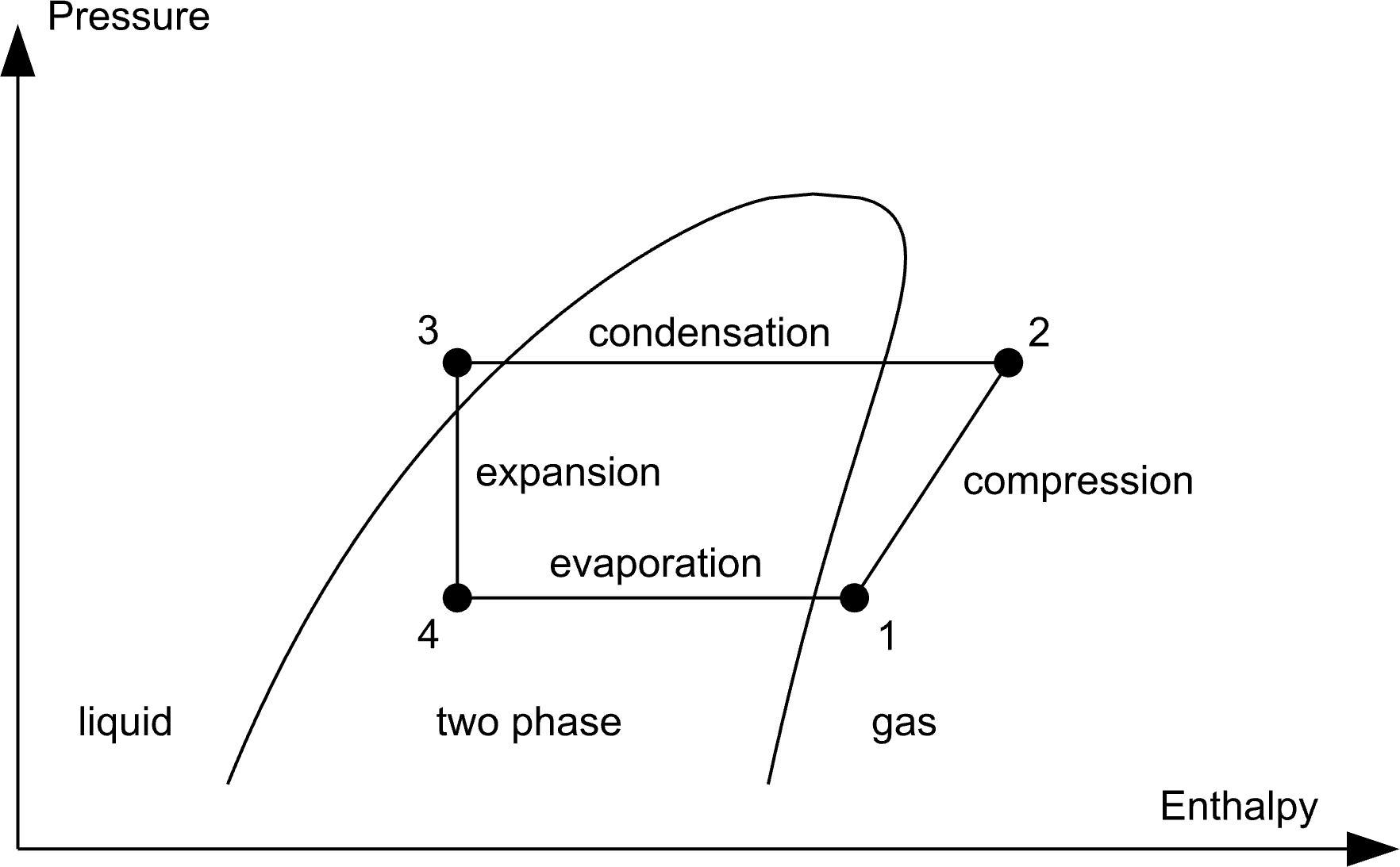
The vapor-compression refrigeration cycle is the most common thermodynamic cycle used in refrigerators, air conditioners and heat pumps. It consists of four main processes:
4 → 1 Evaporation: After passing through the expansion valve, the refrigerant enters the evaporator as a cold liquid-vapor mixture (point 4). While absorbing heat from the surroundings, it evaporates completely and becomes slightly superheated before leaving the evaporator at point 1.
1 → 2 Compression: The compressor raises the refrigerant to a higher pressure and temperature. This requires mechanical work and produces hot, high-pressure gas at point 2.
2 → 3 Condensation: In the condenser, the refrigerant rejects heat to the surroundings. It condenses into liquid and is often subcooled slightly before leaving the condenser at point 3.
3 → 4 Expansion: The liquid refrigerant passes through an expansion valve, where its pressure drops abruptly. The expansion is approximately isenthalpic, producing a cold liquid-vapor mixture that enters the evaporator and the cycle repeats.
Refrigeration, Air Conditioning and Heat Pumps
The thermodynamic cycle is identical for refrigerators, air conditioners and heat pumps. The difference lies only in which heat exchanger is considered useful.
- In a refrigerator or air conditioner, the evaporator is the useful heat exchanger because it removes heat from the cooled space.
- In a heat pump, the condenser is the useful heat exchanger because it delivers heat to the building.
The calculator below therefore evaluates both the cooling COP and the heating COP from the same refrigeration cycle.
Interactive Refrigeration Cycle Calculator
Use the interactive refrigeration cycle calculator below to analyse a single-stage vapor-compression cycle. Specify the evaporation and condensation temperatures, subcooling, superheating and compressor isentropic efficiency. The default example uses R134a, but you can replace it with R290 (propane), R1234yf or any other supported refrigerant.
The calculator determines the thermodynamic state at each point of the cycle, including pressur, temperatur, enthalpy and entropy. Separate results are shown for refrigeration and heat-pump operation, including COP, Electrical power, refrigerant mass flow rate and suction volume flow rate. rate.
Because Calcumber is a full-featured engineering calculator, you can freely modify, extend and share the calculation. Add your own equations, compare different refrigerants or adapt the example to your application.
Click the button or the calculation table below to open the interactive refrigeration cycle calculation in the Calcumber Web App.
| === Select Fluid === | |
| load fluid R134a | 1 |
| === Define Input === | |
| Evaporation temperature: T_ev = -10 °C | -10 °C |
| Condensation temperature: T_cond = 45 °C | 45 °C |
| Subcooling: ΔT_sc = 5 °C | 5 °C |
| Superheating: ΔT_sh = 10 °C | 10 °C |
| Isentropic efficiency: eta_is = 60 % | 60 % |
| Cooling / heating capacity: Qt = 8 kW | 8 kW |
| === Pressure Levels === | |
| Evaporation pressure: p_ev = p(T_ev) | 2.00603 bar |
| Condensation pressure: p_cond = p(T_cond) | 11.5992 bar |
| === Point 1 - Compressor Inlet === | |
| Superheating: T1 = T_ev + ΔT_sh | 0 °C |
| Enthalpy: h1 = h(T1, p_ev) | 401.181 kJ/kg |
| Entropy: s1 = s(T1, p_ev) | 1.76511 kJ/(kg*K) |
| === Point 2 - Compressor Outlet === | |
| Isentropic compression: h2s = h(s1, p_cond) | 439.736 kJ/kg |
| Actual compression: h2 = h1 + (h2s - h1)/eta_is to kJ/kg | 465.440 kJ/kg |
| Discharge temperature: T2 = T(h2, p_cond) | 85.0030 °C |
| === Point 3 - Condenser Outlet === | |
| Subcooled liquid temperature: T4 = T_cond - ΔT_sc | 40 °C |
| Subcooled liquid enthalpy: h3 = h(p_cond, T4) | 256.382 kJ/kg |
| === Point 4 - Expansion Valve Outlet === | |
| Isenthalpic expansion: h4 = h3 | 256.382 kJ/kg |
| COP, Power, Mass Flow Rate | |
| ========================== | |
| === Cooling === | |
| Cooling COP: COP_c = (h1 - h4)/(h2 - h1) | 2.25335 |
| Electrical power: P_el_c = Qt / COP_c | 3.55026 kW |
| Refrigerant mass flow rate: mt_c = Qt / (h1 - h4) to g/s | 55.2492 g/s |
| Suction volume flow rate: Vt_c = v(T1, p_ev) * mt_c to m3/h | 20.7798 m3/h |
| === Heating === | |
| Heating COP: COP_h = (h2 - h3)/(h2 - h1) | 3.25335 |
| Electrical power: P_el_h = Qt / COP_h | 2.45900 kW |
| Refrigerant mass flow rate: mt_h = Qt / (h2 - h3) to g/s | 38.2670 g/s |
| Suction volume flow rate: Vt_h = v(T1, p_ev) * mt_h to m3/h | 14.3926 m3/h |
Extend the Calculation
Calcumber is a full-featured engineering calculator. Modify and extend the refrigeration cycle calculation to answer questions relevant to your own application.
- Investigate how increasing superheating or subcooling affects the COP and compressor discharge temperature.
- Compare R134a and R290 under identical operating conditions.
- What air volume flow is required for an air-to-water heat pump?
- How much electrical energy is consumed during 2,000 full-load hours per year?
- Add pressure drops in the evaporator and condenser.
- Include compressor volumetric efficiency.
- Model heat exchangers using thermal resistances instead of fixed evaporation and condensation temperatures.
- Can you extend the calculation to model a transcritical CO₂ refrigeration cycle?